|
Figure 1: Aurora solar car |
DESIGN OF AN IN-WHEEL MOTOR FOR A SOLAR-POWERED ELECTRIC VEHICLE
Abstract
The design of an in-wheel electric motor for the solar-powered vehicle "Aurora", entered in the 1996, 3010 km, Darwin - Adelaide World Solar Challenge solar car race, is described. The brushless DC motor was more efficient (97.5% compared to 92-95%) and lighter (8.3 kg compared to 12-16 kg) than all other direct-drive motors, and more efficient than all motor/gear combinations, in the race. This was achieved by the use of high flux-density rare-earth magnets, and computer aided optimisation of an axial-flux configuration consisting of a Halbach magnet array and an ironless air-gap winding.
|
Figure 1: Aurora solar car |
The paper reports the design of a very efficient, light-weight, direct-drive, in-wheel motor, ultimately placed in the single front wheel of the Aurora solar car (Figure 1). The efficiency of the motor was optimised, incorporating a mass penalty to allow for tyre rolling resistance. Cost was not considered in the design.
Direct-drive motors were first used in the World Solar Challenge in 1993 by 3 teams: Honda, Engineering College of Biel, and Northern Territory University (Storey et al (1)). Several other teams followed in 1996. Aurora Vehicles Association introduced a novel "wing section" car shape in 1993, which required a single front wheel and two rear wheels, rather than the more common reverse configuration (Baddeley et al (2)). The mass of the front wheel had to be low to avoid lifting on rough roads at high speed. The specification given below calls for a continuous torque per unit active mass of at least 3.24 Nm/kg, more than double the value peviously achieved by the earlier direct-drive motors, or by a typical induction motor of similar rating (but of much lower efficiency), and a torque per unit volume of at least 3700 Nm/m3, also at least double that of a typical induction motor.
To win the race a car needs to convert the maximum amount of solar energy, and use this energy well. The solar cell efficiency (24% from the University of New South Wales) and the race rules limit the available power to about 1.8 kW for a single-seater car. In decreasing order, the losses are: aerodynamic drag, rolling resistance, controller and motor. A well designed car can potentially average 100 km/h. A typical internal combustion engine road car at this speed uses about 35 kW from the engine and about 140 kW from the fuel.
The specification initially was for two motors, mounted on (or in) the rear wheels, with no fixed limit on overall mass. Direct drive was required to eliminate drive-train losses. The motor was required to fit inside a wheel to reduce aerodynamic drag, and to have maximum efficiency.
TABLE 1- Specification
Continuous output power |
1800 W |
Peak power for 72s (hill climb) |
3.1 x 1800 W |
Mean speed at 100 km/h |
1060 rev/min |
Max. speed at 130 km/h |
1380 rev/min |
Continuous torque |
16.2 Nm |
Peak torque (hill climb) |
50.2 Nm |
Starting torque |
50.2 Nm |
Maximum outside diameter |
360 mm |
Maximum axial length |
43 mm |
Maximum active mass |
5 kg |
Mass penalty |
0.75 W/kg |
Initial work revealed that the complete specification could be met with a single motor, of no more than 5 kg active mass, operating at an efficiency of over 97 %, with total losses of less than 56 W, lower than with two motors, giving the specification in Table 1. This motor could fit in the front wheel, allowing simple steering, and without upsetting the car stabilityat high speed.
3. MACHINE GEOMETRY The machine structure forms a ring, with permanent magnet excitation for low losses, as shown in Figure 2. Several options were considered for the geometry. An arrangement featuring axial flux, an ironless air-gap winding, and outer rotating magnets was selected for the following reasons: Axial flux was chosen because: of inadequate axial length for end windings in a radial-field air gap winding design, double magnet rotors could be mounted on the wheel side walls, the stator winding could be mounted centrally on the axle, winding and magnet discs could be manufactured on flat formers. An air-gap winding was chosen because: the efficiency with toothed structures is less than 96% due to tooth iron loss, a high field is achievable with new permanent magnet materials and special magnet arrangements, more space is available for copper, leading to lower copper loss, eddy current loss is controllable with stranded Litz wire, leading to an efficiency greater than 97%. An ironless stator was chosen because: the performance is similar to that calculated for a stator with a glassy-metal core, which is difficult to assemble and anneal, the mass is minimised for a given air-gap flux, there are no forces on the stator during assembly, the thermal performance was adequate. |
|
Figure 2: Cross-sectional drawing of motor |
4. MAGNET ARRANGEMENT
It was found that the maximum air-gap flux density per unit rotor mass can be achieved with a solid magnet rotor, with no back iron, in an arrangement often called a "Halbach" assembly (see for example Ofori-Tenkorang and Lang (3)), shown in Figure 3. |
|
Figure 3: Halbach magnet array and air-gap winding |
The design chosen uses 4 magnets per pole. The angle of magnetisation of the magnets was varied, and best performance was at angles close to 30 and 60 degrees with respect to the axial direction.
Optimisation predicted that a design with the Halbach magnet arrangement would have approximately 10 W (20%) less loss than an equivalent conventional arrangement of the same total mass, with magnets on backing iron.
5. SOURCES OF LOSS
In the chosen motor design the only sources of loss are: copper loss, eddy current loss in the winding, windage loss, bearing loss.
Copper loss is the dominant source of loss in the winding. The winding MMF pattern was input into ANSYS in 2D, assuming that there is no overlap between phase bands and all currents are sinusoidal. From the calculated torque (using a virtual displacement method) and knowledge of the rated torque, the required MMF magnitude and resulting copper loss was determined.
The loss (Pe) resulting from eddy currents in a round conductor of radius R, resistivity r, and length l, placed in a pulsating magnetic field of peak flux density B and frequency w is (Carter (4)):
Pe = ? B 2w 2l 4/8r (1)
It was assumed that eddy current loss only occurs in the active portion of the winding. To reduce eddy loss, the winding was made of Litz wire, with twisted (transposed) strands to reduce circulating currents.
The internal windage was also calculated from an analytical formula, which determines from the Taylor number that for this machine the flow regime is laminar with vortices.
External windage and bearing losses were assumed to be the same as for a wheel without the motor, so were neglected in the optimisation.
6. DESIGN OPTIMISATION
The design was optimised, initially using Excel and Mathematica, and later using ANSYS 2-D finite-element analysis, to minimise the total loss with the following main further assumptions: The heat transfer coefficient between the winding and the surrounding air is 20 W/m2K, a reasonably high value because most of the air is likely to be rotating with the wheel past the stationary armature winding. Cooling was neglected for peak torque heating. There is no radial variation of magnetic field in the winding, i.e. no end effects. A 3D finite-element solution indicated that the active flux density dropped towards the radial ends of the active portion of the machine, but that the end-windings would link additional end flux. There is no axial variation of magnetic field. The 3-D analysis showed a 10% increase from the centre to a winding edge due to magnet leakage flux. This emphasises the requirement for transposed subconductors. The agap magnetic field is effectively sinusoidal. This was confirmed by emf measurement, and flux density calculation. The flux distribution was nearly sinusoidal at the winding centre, but deviated slightly from this at the winding edge.
6.1 Choice of Pole Number
Between 30 and 60 poles was initially thought sensible for this machine design. Optimisation results shown in Figure 4 suggested that there was a small reduction in total penalty as the pole number was reduced from 60 to 40 poles due to a reduction in eddy current loss, but that any further reduction caused a substantial increase in total penalty. This arises due to the increasing size of the endwindings and flux return paths. A 40 pole design has a pole pitch of the order of 21 mm and a maximum electrical frequency of 460 Hz, both suitable values. |
|
Figure 4: Effect of number of poles |
6.2 Effect of Mass
The mass limit was initially set at 5.0 kg. The results in Figure 5 were obtained with the pole number fixed at 40. As a significant reduction in loss could be achieved by increasing the mass from 5.0 to 6.0 kg, and it was confirmed that the car stability would not be compromised, final calculations were based on an active mass of 6.0 kg. |
|
Figure 5: Effect of active mass |
6.3 Effect of Air-gap Length
The effect of air-gap length is shown in Figure 6. Although gains could be made by reducing the air-gap length below 2.0 mm, the gap was kept at 2.0 mm on each side of the winding to allow for winding encapsulation and mechanical clearance. |
|
Figure 6: Effect of air-gap length |
D.C. motor speed control
Controlling the speed in an electric car using solar energy can not be done by adding resistances in series with the rotor because the solar power is considerably small & unstable . That is why the photo cells are connected to large batteries to store the solar power inside . Therefore , adding resistances in series with the rotor will increase the power losses which we must minimize it as much as we can .
In this application, a chopper has been used . A chopper is an electric circuit used to transform a certain DC value into a desired AC value . The O/P of the batteries is considered as the I/P to the chopper circuit where we can control the final DC value .
Solar energy i/p DC o/pcontrolled value
This can be represented mathematically as ..
V = E + I a R a = Kw f + I a R a +
Then w = V / Kf - I a R a / Kf V E
Since t = torpue = I a / Kf R a
w
= V / Kf - t R a / ( k f )2????????? ??-??????w w
V / Kf
V / Kf
t t
Fig. (1) Fig. (2)
From w / t characteristics , we can conclude that :
Changing t is better than changing Ra .This is from fig(2) ,which represents w /t characteristics {by changing t }, we can notice that there is a wide range of w that leads to easily control the speed but in fig(1) which represents w /t char. { by changing Ra } we can notice that there is a limited range of for controlling the speed .
7. DESIGN RESULTS
Some further design results obtained for the 6 kg motor are shown in Tables 2 and 3. The magnet selected was VAC362HR, a neodymium iron boron material, with Br=1.33 T at 20°C.
TABLE 2- Design results
Mass of copper |
1.2 kg |
Mass of magnets |
4.78 kg |
Total active mass |
5.98 kg |
Mass Penalty |
4.5 W |
Peak air-gap flux density (20°C) |
0.91 T |
Winding |
2 layer, fully pitched |
RMS current density |
3.12 A/mm2 |
Total force of attraction on rotor faces |
4900 N |
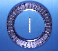
Two motors were fabricated. A magnet ring is shown in Figure 7 and a stator winding in
Figure 8. The stator was naturally air cooled.
8. EXPERIMENTAL RESULTS
Tests were conducted to determine the motor resistance, inductance, emf constant, emf waveform, torque constant, no load losses, load losses, efficiency and temperature rise.
|
|
Figure 7: Magnet ring |
Figure 8: Stator winding |
The no load losses were separated by retardation tests with magnets and stator removed (bearing loss and external windage), dummy magnets and stator inserted (inner windage added), actual magnets replaced (winding eddy loss added) and a motor no load test (total loss as confirmation).
The load tests were conducted by mounting the wheel between two shaft torque transducers and allowing the tyre to rest with the appropriate force on a rotating flywheel loaded with a DC generator. Depending on the direction of rotation, one torque transducer output shaft was locked to react against the wheel motor.
The supply for the load tests and the race was a quasi-square-wave MOSFET inverter. The motor synchronous inductance was only 22 mH (0.01 p.u.) so external inductors of about 100 mH (0.05 p.u.) per phase were used to limit the current ripple resulting from the switching action of the converter
The rms value of the quasi-square-wave current was 5% higher than the ideal sine wave, leading to 10% extra copper loss (»4 W), but saving some inverter switching loss.
Input power, voltage, current and supply frequency (speed) was measured with a calibrated Voltech PM3000A, 0-500 kHz, 0.1% digital power analyser, and the torque transducers were calibrated Vibrometer TM series, 0.2%. The resistance was measured with a Cropico digital milliohmmeter.
Some results for motor 2 are compared with design values in Table 3 (the corresponding efficiency of motor 1 was 97.5%), and the efficiency predicted from the measured results is plotted against speed in Figure 9, with 10 mW added to the phase resistance for leads and connections.
TABLE 3- Comparison of design and measured results for 6 kg motor at 16.2 Nm, 1060 rev/min, 1800 W, 20°C
Design |
Motor2 |
|
Axial gap between magnet rotors (mm) |
9.3 |
10.0 |
Phase resistance (W) |
0.0723 |
0.0997 |
RMS Fundamental phase current (A) |
9.6 |
11.34 |
LN rms emf (V) |
61.9 |
54.3 |
Emf constant (LN rms emf/speed in rad/s) |
0.56 |
0.47 |
Torque constant per phase (Nm/A) |
0.56 |
0.49 |
Copper loss (W) |
20.0 |
38.6 |
Eddy current loss (W) |
4.6 |
2.7 |
Windage (design for 2mm gap each side) (W) |
0.4 |
2.1 |
Total Loss (W) |
25.0 |
43.4 |
Efficiency (%) |
98.6 |
97.9 |
Temperature rise (K) |
10.2 |
18.3 |
Temp. rise after a further 72 s at 50 Nm (K) |
37.5 |
42 |
Temperature rise at 30 Nm (K) |
30.0 |
60 |
|
Figure 9: Efficiency of Motor 2 at various load torques |
The performance at 30 Nm (the approximate thermal limit rating with natural cooling) is contrasted with that of a typical 30 Nm, 6 pole induction motor and an internal combustion engine and drive train in Table 4. The final total weight was 8.3 kg including magnet carriers, stator encapsulation, central support and terminations. An inverter mass and volume should strictly be added to give a fairer comparison with the IC engine.
TABLE 4- Comparison of Aurora motor at 30 Nm with 30 Nm, 950 rev/min induction motor and internal combustion engine and drive train
Torque/ total weight ratio |
Torque/ total volume ratio |
Efficiency |
Losses |
|
Nm/kg |
Nm/m3 |
% |
% |
|
Aurora |
3.61 |
10135 |
96 |
4 |
Induction |
0.80 |
1500 |
82 |
18 |
IC engine |
1.5 |
1970 |
25 |
75 |
A further comparison is given in Table 5, with the earlier direct-drive solar-car motors (The efficiency of the Biel motor is given in (1) as 97.5 % at 14.9 Nm, 900 rev/min (1.4 kW), but 1996 information from Storey gave this as 95%). The new Aurora motor has a lower mass and higher efficiency than all the other motors.
TABLE 5- Comparison of Aurora performance with 1993 direct-drive solar car motors (1)
Aurora |
Honda |
Biel |
NTU |
|
Total weight (kg) |
8.3 |
12.8 |
12.0 |
16.5 |
Nominal speed (rev/min) |
1060 |
1000 |
900 |
600 |
Nominal torque () |
16.2 |
14.3 |
14.9 |
22.3 |
Thermal limit torque (Nm) |
30 |
14.3 |
14.9 |
55.7 |
Nominal torque/total weight ratio (Nm/kg) |
1.95 |
1.12 |
1.24 |
1.35 |
Efficiency (%) |
97.5 |
95 |
95 |
92 |
9. CONCLUSION
This report has detailed a motor design which has been optimised for high-efficiency, in-wheel operation. The design uses an axial field, air-gap winding in order to produce 1800 W at 1060 rev/min, with 6.0 kg of active mass at an efficiency of more than 97.5 %. The design is thermally suitable for twice the required rating.
1. Storey JVW, Schinckel AET, Kyle CR, 1994 "Solar Racing Cars 1993 World Solar Challenge" Australian Government Publishing Service, Canberra
2. Baddeley V, Humphris C, Pudney P, 1994 "The Aurora Q1 solar-powered racing car" ANZAAS Congress, Australia
3. Ofori-Tenkorang J and Lang JH, 1995 "A comparative analysis of torque production in Halbach and conventional surface-mounted permanent magnet synchronous motors", IEEE IAS Annual General Meeting, Orlando, Oct., 657-663
4. Carter GW, 1967 "The electromagnetic field in its engineering
aspects" Longmans, 2nd ed., 254