INTRODUCTION:
Industry commonly uses automatic machines and automated processes for discrete item production , batch process. These automatic machines and processes where developed to mass produce products, control very complex operations. They replaced much human decision, intervention and observation.
Machines were originally mechanically controlled , then they were electromechanically controlled , and today they are often controlled by programmable controllers. The control of processes can be divided into five categories:
It was the first step away from mechanical control .It is extensivly used in industry today . The relay system has limited applications where it is used in small and simple system , where there is no need to change the function of the system ,it costs if it is used in large and complex systems .
2-Hardwired Electronic Control:
As control functions became more complex the need for electronic timers, counters increased. They are reliable , although system troubleshooting is more complex than relay control system . They lake wiring flexibility when needed to change the function of the system , besides that it costs.
3-Programmable Hardwired Electronic Control:
The introduction of programmable elements such as timers , counters and sequencers into the control system brought flexibility and multifunction to the system design and they allowed the function of the machine or process to be changed without costly rewiring.4-Programmable Logic Controller (PLC):
In 1978 the National Electrical Manufacturers Association (NEMA) defined programmable controllers as “ A digitally operating electronic apparatus which uses a programmable memory for the internal storage of instructions for implementing specific functions , such as logic , sequencing , timing, counting and arithmetic, to control through digital or analog input/output , various types of machines or process”.
Each time the machine function or process is changed, no wiring changes are necessary.
5-Computer Control :
Computers , particularly personal computers , are being accepted as useful devices for machine and process control .Although computer costs are comparable with PLC’s and can perform complex computations required for industrial process ,they are not designed to operate in a harsh industrial environment , so PLC’s are preferred in such industrial environment.
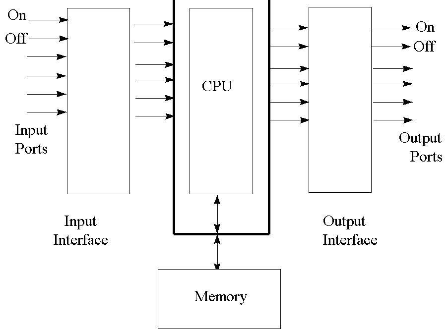
29.1.PROGRAMMABLE CONTROLLER HARDWARE:
29.1.1.Programmable Controller Basic Structure:
T
here are six components found in all programmable controller systems :
PLC basic structure
Fig 29.1.
1-Input assembly : There are two forms of input signal AC and DC .Input assemblies are required to accept both high AC and DC voltage and low DC voltage. A common input assembly is shown in fig.(29.2) while the function of each section is as follows :
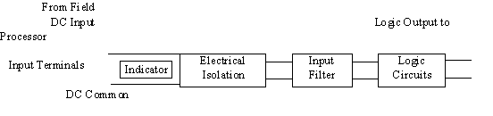
Input assembly block diagram
fig.29.2
2-Output assembly : It consists of a number of sections (see fig.(29.3)).
Data Output
From
Processor
Output assembly block diagram
fig.29.3
3-Processor Unit:
Which is the PLC’s system decision-making unit .It stores input and output modules in the memory , then scan the program and make the decision according to input and output and program instruction .
Processor operational indicators: There are number of switches which change the processor’s modes of operations. There are four modes of operations of a PLC which are :
The processor unit will have certain indicators to provide system diagnostic information to the operator, which are :
4-
Memory: The memory that stores the user program and the operating program may be one of the known types (e.g. magnetic tape ,floppy disk ,hard disk and laser disk ), but the most famous types which usually hold the PLC user program are core, magnetic bubble and random access memories.Most programmable controllers have memory expansion modules or socket space available on the processor printed circuit board to expand the memory size if necessary.
Memory organization: The user must know exactly where the program will be located in memory to be able to address the instruction for execution .The memory of the PLC can be divided into three parts:
timer /counters
locations
no access by user
Memory organization block diagram
fig.29.4
5-Power supply:
PLC system requires two power supplies one provides power necessary for field devices and output loads to operate and is provided by PLC user .The second power supply is provided internally or as a module of the PLC system ,this power supply provides DC current to operate the processor logic circuitry and input/output its value depends on the type of ICs within the system (TTL 5v,CMOS 3-18v) .
If RAM is volatile, a back-up battery is used to supply power to the memory during power failures. Some PLC manufacturers provide a battery low indicator .
6-Programming units:
It allows the PLC user to enter, edit and monitor programs by connecting into the processor unit and allowing access to the user memory .
The programming unit can be a single line LED display or a keyboard and a visual display u(VDU) ,the programming unit communicates with the processor via a serial or parallel data communications link(will be discussed later).Removing the programming will not affect the operation of the user program .A computer with appropriate software can also act as a program terminal ,making it possible to carry-out the programming away from the physical location of PLC .When the program is complete it is down loaded and saved in PLC .
29.2.LOW COST MORE EFFICIENCY:
The PLC is not a separate device operating in isolation ,even in the simplest application it is the central section of an overall control system .
PLC helps in reducing costs and increasing efficiency by:
Despite of all these advantages PLC may show certain disadvantages:
29.3.MULTITASKING:
PLC's can be used in systems where a single PLC may control more than one machine or processor simultaneously , which is termed multitasking .PLC's used in multitasking are of large variety with more than 128 input output connections the advantage of multitasking PLC's is that once they are installed and operating, maintainance and fault finding are easier and program modification is simple .The disadvantage of multitasking that it reduces flexibility in machine and control applications because designing of machines and hard ware is to suit a single application.29.4.INTERFACING DIGITAL DEVICES:
Digital devices are connected directly to the input of the PLC's but care must be taken that voltages and power levels are matched input devices maybe one of the following: mechanical ,transistor ,proximity ,photoelectric switches ,reed switches/relays ,encoders ,temperature and pressure switches(each will be discussed briefly in appendix A) .These switches are used according to the application to represent the digital input of the PLC.
Digital output ports controls solenoids ,relays ,contactors and motors which in turn control machine actions.
29.5.INTERFECING ANALOG DEVICES:
The need to analog to digital converters (A/D) and digital to analog converter (D/A) , multiplexers ,demultiplexers rises to overcome dealing with analog signals in digital PLC's. The main rule when interfacing analog signals is to match voltage levels and insure that the impedance of the sourcing circuit is less than or equal to that of its load circuit for better power transfer to the load circuit and this is done by using simple
circuits for example using potential divider for reduction of voltage level of input signal or by using inverting and non-inverting amplifier to increase voltage level .Transducers may be used to convert physical quantities (e.g. temperature ,displacement) into analog signals .
29.6.CONNECTION OF PERIPHERALS:
A peripheral is any device that can be connected to PLC and not a part of it and it is considered a support device .the variety of peripheral devices is large and includes:This peripheral devices are connected to the PLC through communication ports (will be discussed in a following section.).
Connection to
other equipment Controlled machine
or process
29.7.DATA COMMUINCATION:
The programmable controller have the ability to communicate with various devices using data communication techniques. The earliest PLC’s was able to communicate with audio cassette recorders, as well as to document program information using printers . Later generations of PLC’s are able to communicate with other types of microprocessor-based devices .PLC’s should have more than one input and output terminals (ports) to improve it’s operation while connected to various data communicating devices. Ports are classified into serial and parallel ports. Serial connection for data communication requires only two wires through which the data word is transmitted bit by bit .Serial communication can be transmitted over greater distances than parallel communication .Parallel data communication is used over short distances of approximately 10 meters ,although of this ,it is preferred to communicate between PLC and printer since it provides the minimum signal loss and very reliable in high speed transmission. The transmission medium needed may be any electronic communication circuit . The channel between transmitter and receiver may be co-axial cable ,radio links ,optical fibers .
PLC processor Local area network
module connects the PLCat different locations communications
communications
together module moduleSerial
connection
Parallel Serial
connection
connection To controlSerial room monitor
connection Public switched
telephone network
Data communications and PLC’sfig.29.7
29.8.APPLICATIONS OF PLC’S IN LOCAL AREA NETWORKS(LAN
’S): The importance of LANs increased in the past years due to the need of increasing the communications and quick data transfere among working groups in a same field . LANs provided this needs .In industrial environment the need to connect the PLCs to the LAN is of a great importance to follow the PLC systems and reprogram it , when necessary, from distant offices instead of human presence in such industrial environment .Most LANs are defined by the open system interconnection (OSI) model . The discribtion of the OSI model ,from the highest to the lowest , is as follows:
29-7
CHAPTER 29
When connecting a PLC to a network, a protocol is reached between the PLC programing languague and the network programming language(a protocol is an intermediate language inserted between two systems using two different languages).The most famous protocol used with PLC’s is the manufacturing automation protocol(MAP).
29.8.1.Network Sharing Techniqes:
Time-sharing techniqes helps in connecting more than one user to the system and communicate with other user working at the same time . The commonly known time-sharing techniqes are time-division multiplexing (TDM) and frequency-division multiplexing (FDM) and polling .TDM provides the transimission of data from each one of a number of data sources to the reciver , one block of information at a time through a common transimission medium . At the reciver end , demultiplexing is done to separate the time-division multiplexed transimated data . TDM is used to connect a number of PLC’s to a single master computer . This method is preferred when there is a low speed program to allow the multiplexing and demultiplexing operation to be done .
FDM is very sutable to a medium with wide bandwidth and were data uses an exclusive frequancy bandwidth . It’s advantage is that the data path is continous between the transmitter and the reciver .
Polling and time-divison multiplexing works with the same basics for polling device calls up infoormation from the PLC’s in a cyclic manner . Time reduction is achived by placing priorities on the polled device or by making the PLC signal the polling device that a change of status has accured .
multiplexer demultiplexer
Time division multiplexing
fig.29.8
Frequency division
Frequency-1 multiplexer Demultiplexer
Frequency-2
Frequency-3
Frequency-4
Frequency-division multiplexing
fig.29 .9
29.13.APPLICATIONS ON PLC:Through this section we’re concerned with some applications of PLCs from simple systems to more complicated systems ,in each example we’ll concentrate on the controlled problem ,description of control element ,but we’ll not give the programming solution because programming in PLCs could be written in any language (BASIC,SATA….etc).
29.13.1.Proportional temperature control:
The control problem:
In this example we need PLC to act as a proportional temperature controller .As shown in figure the operation of the system is to compare the actual temperature T1 of the heated mass with the needed temperature T2 ,the output signal from the controller is proportional to (T2-T1)=K*E (K: is the proportional gain constant )
E=T2-T1
K*E
closed loop temperature control system
fig.29.12
Description of control element:
As shown in figure an A/D is required to sense the analog voltage produced from the thermocouple amplifier the amplifiers gain is adjusted so that the temperature output matches the A/D input over the required temperature range .Using a D/A to vary heater power allows very fine control to be exercised.
Thermocouple
Amplifier
SC
EOC
Set point stored
in the controller
Non-inverting
amplifier
12v(2A)
2N3035
Darlington 2N3055
pair
Input/output connection for
the temperature control system
fig.29.13

